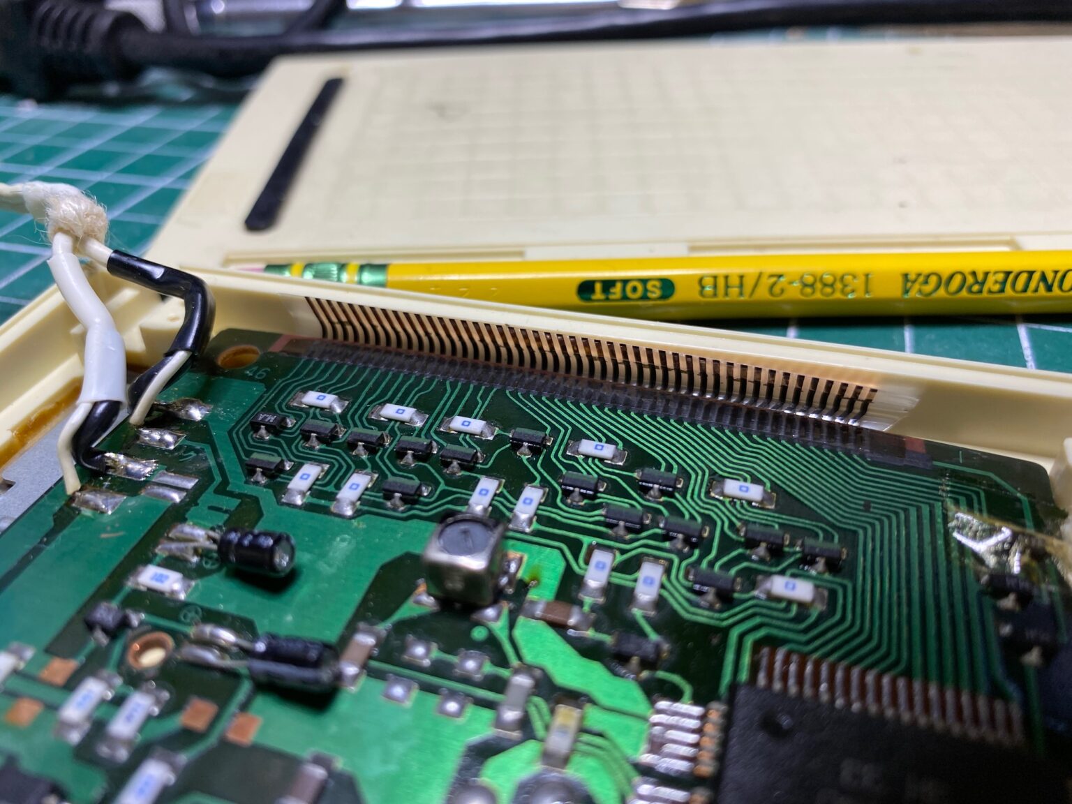
A common failing of older PT-7’s is that the keyboard no longer responds to touch. This can be because the the foil ribbon connector from the keyboard to the PCB has become disconnected.
Original Construction
After asking for help on the EEVblog, All About Circuits, and Reddit forums, the consensus seems to be that the foil ribbon cable was originally secured to the PCB with a method called ACA Bonding. An anisotropic conductive adhesive (ACA) has conductive particles scattered in it, enough of them so that it conducts in the Z-axis (the thickness of the tape), but still acts as an insulator along the X and Y axis.
ACAs developed in the late 1970s and early 1980s. In the very early years, ACAs were made from rubber, acrylic, and other adhesive compounds.1 The PT-7 keyboard connection was made with an older version of the material, obviously, and while we don’t know exactly what they used, the black surface seems to suggest that this may have been a rubber-based ACA.
Disassembly
- On the back side of the keyboard are three tiny screws; remove these
- On the side where the screws were, lift the case panel a ”very small amount,” just enough so that you can grasp the plastic and pull.
- While wiggling gently, pull the case panel horizontally, in the direction of the cable hole; the tabs will slide out from under the metal edge on the opposite side.
[photos to come]
Troubleshooting
To know if this method of repair will help in your case:
- Use a piece of regular cellophane tape to adhere the foil connector back over the connectors on the PCB; be sure to align the connectors precisely
- With a piece of firm foam and a hard backing, like a stick, apply even pressure to all of the contacts on the connector
- It is likely at this point that you are unable to apply absolutely even pressure, but if even a few of the keys are now responding to touch, this bodes well for this repair.
Mechanical repair method
This method was designed by CYBERYOGI =CO= Windler, and more information is available from the PT-7 page on CYBERYOGI =CO= Windler’s keyboard site "WarrantyVoid". I quote the relevant bits here:
When I took the keyboard foil stack out for closer inspection, I noticed that the upper and lower contact foils are (instead of being made from one folded piece) connected in the upper right corner by another such glue joint, which also fell apart once I tried to take out and photograph the intermediate perforated insulation layer. Without success I tried to reconnect this end with a kitchen foil welder (did not even melt), SMD hot air soldering gun (up to 160°C, did rather warp a little without staying attached). These foils have copper paint traces (shiny from the transparent top) covered with conductive carbon or graphite paint. A careful test with SMD soldering iron revealed that despite apparent copper layer even at lowest possible heat molten solder destroys the paint and tends to melts the ancient foil. (Modern copper foil cables can be soldered.) So I simply aligned top and bottom foils with adhesive film, sharply rolled both contact ends together (held into place with adhesive film) and squeezed them under the sheet metal cover inside the case, which seems to work properly. I increased the pressure by installing short screws in the 2 unused screw holes at its sides. – This was the easier part.
Unfortunately it turned out much more difficult to reattach the foil cable to the PCB. First of course hold it with adhesive tape into place, but the problem is that it needs firm permanent equal squeeze on all pins to make reliable contact, thus a strip of (window isolation) foam rubber on top has to stay pressed in place. Unfortunately in the PT-7 keyboard unit both case top and bottom are overly floppy and only bulge out instead of compressing the strip, and (unlike a glass LCD) also the PCB is rather flexible. So I tried to make several kinds of metal brackets (kind of safety pin or hair clip style) to clamp the PCB without warping the case, which still bent the PCB and didn’t work too well. (I even broke a key matrix transistor by collision with pliers and replaced it with an SMD diode.) Against floppy parts help only floppy disks, so I finally made 2 short vertical clamps from the sheet metal sliders of 2 broken 3.5” diskettes. Bent around the entire foil cable (that I protected from the sharp metal rims by fabric adhesive tape) at the PCB rim, it applies much evener pressure. But even this still needs some metal reinforcement and a short foam strip on top that is squeezed by the case cover. Although it seems to work, it is still very prone to bad contacts. (I am not even sure if I damaged the foil harness elsewhere.) And be careful, there is another glue joint lurking between foil cable and keyboard foil stack, that is certainly of the same brittle stuff.
Adhesive repair method
This method is a work in progress by Mark Boszko. I will update this as I progress through the repair. —Mark
[photos to come]
3M makes an Electrically Conductive Adhesive Transfer Tape 9703 (data sheet). It is very, very expensive by the roll, but small 2×6" pieces are available on Amazon and from Adafruit. I have ordered one of these sheets, and plan to use it to replace the old ACA. This newer film does not require a full heat set that the older ACAs did, though they do suggest warming the tape to increase ”wetting” of the film. Here are the relevant Bonding and Clamping sections of the data sheet.
Bonding
- To obtain maximum adhesion, the bonding surfaces must be clean and dry.
- Pressure must be applied to the bond line after assembly to wet the substrates with 3M™ Electrically Conductive Adhesive Transfer Tape (ECATT) 9703 and to engage the conductive particles with the substrates to make electrical connection. Mechanical pressure (roller, metal bar) or finger pressure at 15 psi (0.10 Mpa) or greater is suggested. Heat may be applied simultaneously to improve wetting and final bond strength.
- 3M ECATT 9703 should be applied between 60°F – 158°F (15°C – 70°C). Tape application below 50°F (10°C) is not recommended because the adhesive will be too firm to wet the surface of the substrate, resulting in low adhesion.
- Adhesion builds with time, up to 24 hours may be required to reach final adhesion values.
Mechanical Clamping
To assure electrical resistance stability of 3M ECATT 9703 in any flexible circuit interconnection application, a mechanical clamp or other compressive force (i.e. foam strip held in compression over bond area.) should be considered in the design of the application. Any stress inherent in the assembly design (i.e. tensile, shear, cleavage) or temperature excursions (encountered through normal product use) applied to the bond area could result in an electrical open in the bonded circuit over time when no clamp or mechanism for maintaining a constant compressive forces is used. A well designed mechanical clamp will reduce the environmental stress on the bond line and improve the electrical reliability of the bond. In addition, the temperature operating range for the adhesive can be improved with a properly designed mechanical clamping system to ensure the conducting particles in the 3M ECATT 9703 maintain electrical contact. Several types of mechanical clamps have been used successfully including foam strips attached to lids or cases and screw-attached plastic clamps. Contact your 3M Technical Service Engineer for further information about mechanical clamping.
While I wait for the ACF order to arrive, my one question is: will the new film work if I place it on top of the old film, or should I strip off the old film entirely?
Update
I attempted the repair, but it was not as successful as I had hoped. The likely cause, it seems to me, is that I was unable to remove the original ACA by any means that would not also destroy the original circuit. Thus, I was trying to layer two anisotropic films, and if their conductive particles did not line up exactly (a low probability), then no connection would be made. Perhaps the mechanical solution is the best idea after all.
I wonder if there’s a better solution here? Comments and guggestions welcome.
- “Anisotropic conductive film”, Wikipedia, retrieved 2020-02-16 ↩
Affiliate disclosure. This post contains affiliate links; if you buy through one, I may earn a small commission, at no extra cost to you. As an Amazon Associate I earn from qualifying purchases.
Leave a Comment